Mitsubishi Outlander: General Information
F6AJA and W6AJA models have been established. For the AWD system mounted to some vehicles, based on the electronic control AWD which distributes the driving force to the rear wheels, the driving force control between front right and left wheels has been improved additionally, and S-AWC (Super All Wheel Control) for integrated control with Active Stability Control (ASC) and ABS has been adopted.

TRANSAXLE
The transaxle is made up of the torque converter and gear train. A 3-element, 1-stage, 2-phase torque converter with built-in torque converter clutch is used. The gear train of F/W6AJA transaxle consists of 3 sets of multi-disc type clutches, 2 sets of multi-disc type brakes, and 2 sets of planetary gears which are composed of a sun gear, carrier, annulus gear, and pinion gear.
TRANSAXLE CONFIGURATION DRAWING

COMPONENTS AND FUNCTIONS

FUNCTION ELEMENT TABLE

×: Function element −: Not applicable
SECTIONAL VIEW
<F6AJA>

- Converter housing
- Oil pump
- 3-5 reverse clutch
- Front planetary gear
- Low clutch
- Output gear
- Low and reverse brake
- One-way clutch
- 2-6 brake
- High clutch
- Reduction planetary gear
- Rear planetary gear
- Side cover
- Reduction pinion gear
- Idler gear
- Final gear
- Differential case
- Input shaft
- Torque converter
<W6AJA>

- Converter housing
- Oil pump
- 3-5 reverse clutch
- Front planetary gear
- Low clutch
- Output gear
- Low and reverse brake
- One-way clutch
- 2-6 brake
- High clutch
- Reduction planetary gear
- Rear planetary gear
- Side cover
- Reduction pinion gear
- Idler gear
- Final gear
- Differential case
- Input shaft
- Torque converter
STANDARD SHIFT PATTERN CONTROL
UPSHIFT PATTERN

DOWNSHIFT PATTERN

TORQUE CONVERTER CLUTCH CONTROL
6TH GEAR RANGE

5TH GEAR RANGE

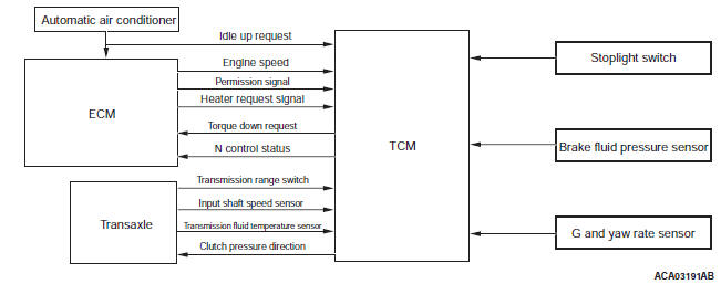
IDLE NEUTRAL CONTROL
The originally engaged starting clutch is slid to block the driving force (creep) which is generated when the vehicle is stopped with D range, improving the fuel consumption by reducing the load.
CONTROL SYSTEM DIAGRAM

SUPER ALL WHEEL CONTROL (S-AWC)
The S-AWC consists of two electronic couplings for longitudinal driving force control and lateral driving force control and the AWC-ECU for control of those two. The AWC-ECU is connected to sensors and other ECUs via the CAN communication line for detecting driver's operation and vehicle behavior. In addition, the S-AWC control mode selector and indicator are provided for switching and displaying the control status.
System configuration

System connection diagram

Control schematic diagram

(1) ELECTRONIC CONTROL COUPLING (FOR LONGITUDINAL DRIVING FORCE CONTROL)
With the electronic control coupling installed in the rear differential, the driving force distribution to the rear wheels is controlled according to the driving status.
(2) ELECTRONIC CONTROL COUPLING (FOR LATERAL DRIVING FORCE CONTROL)

The same electronic control coupling mechanism used for the electronic control AWD is installed in the transfer, and the driving force distribution to the front right and left wheels is controlled.
(3) AWC-ECU
With each sensor value acquired from the CAN communication and operation information of other ECUs, optimum driving force control amount is calculated and the control current for the two electronic control couplings is controlled.
Compared with the electronic control AWD ECU, the performance of the microcomputer is enhanced, resulting in improved accuracy and speed of calculation.
(4) SENSOR INFORMATION
Compared with the electronic control AWD ECU, the sensor information used for control has been added extensively. As a result, the vehicle driving status is judged accurately, achieving the control with good response and precision.

NOTE: ×: Used for control −: Not used
(5) S-AWC CONTROL MODE SELECTOR
Three control modes can be selected using the dial switch installed to the floor console.
(6) INDICATOR
The S-AWC control mode is always displayed on the upper part of multi information display.
On the information screen, a special screen to display the S-AWC operation status is established. The driving force control status between the front and rear wheels are displayed in the center, and the driving force control status between the front right and left wheels is displayed in right and left.

Specifications
SERVICE SPECIFICATIONS

LUBRICANT


