Mitsubishi Outlander: Symptom Procedures
Inspection Procedure 1: TCM cannot communication with scan tool.
TCM POWER SUPPLY CIRCUIT

SYMPTOMS
TCM cannot be turned ON.
PROBABLE CAUSES
- Damaged wiring harness and connectors
- Malfunction of TCM
DIAGNOSTIC PROCEDURE
STEP 1. Check the following connector:
- A-18X CVT control relay connector
- C-38 TCM connector
Check each terminal for imperfect contact.
Q: Is the check result normal?
YES : Go to Step 2.
NO : Repair the defective connector.
STEP 2. Check for open circuit in the wiring harness between the relay box connector and the TCM connector.
- Between A-18X CVT control relay connector (terminal No.3) and C-38 TCM connector (terminal No.12)
- Between A-18X CVT control relay connector (terminal No.3) and C-38 TCM connector (terminal No.25)
Q: Is the check result normal?
YES : Go to Step 3.
NO : Repair the wiring harness.
STEP 3. Check for open circuit in the wiring harness between the TCM connector and the ground.
- Between C-38 TCM (terminal No.13) and ground
- Between C-38 TCM (terminal No.26) and ground
Q: Is the check result normal?
YES : Go to Step 4.
NO : Repair the wiring harness.
STEP 4. Retest the system.
Recheck the trouble symptom.
Q: Does the malfunction take place again?
YES : Replace TCM.
NO : Intermittent malfunction
Inspection Procedure 2: Vehicle Creeps in the N Range.
SYMPTOMS
Engine torque is transferred to the driveshaft in the N range, and the vehicle consequently moves forward or rearward.
PROBABLE CAUSES
- Malfunction of the transmission range switch
- Malfunction of CVT assembly
- Damaged wiring harness and connectors
- Malfunction of TCM
DIAGNOSTIC PROCEDURE
STEP 1. M.U.T.-III data list
Item 49: Transmission range switch
Check that the service data changes when the selector lever is moved to all ranges.
Q: Is the check result normal?
YES : Go to Step 2.
NO : Go to Step 3.
STEP 2. Check of the transmission range switch and shift control cable
Q: Is the check result normal?
YES : Go to Step 4.
NO : Adjust the transmission range switch and the control cable.
STEP 3. Transmission range switch continuity check
Q: Is the check result normal?
YES : Go to Step 4.
NO : Replace the transmission range switch.
STEP 4. Retest the system.
- Replace TCM.
- Recheck the trouble symptom.
Q: Does the malfunction take place again?
YES : Replace the CVT assembly.
NO : The inspection is complete.
Inspection Procedure 3: Shock is experienced during N to D and/or N to R shifting operation.
SYMPTOMS
Deep shock is experienced when the selector lever is moved from the N to R range or from the N to D range.
PROBABLE CAUSES
- Abnormal line pressure
- Malfunction of TCM
- Malfunction of CVT assembly
DIAGNOSTIC PROCEDURE
STEP 1. Engine idling speed check
Q: Is the check result normal?
YES : Go to Step 2.
NO : Refer to the "Engine troubleshooting". STEP 2. Line pressure check
Carry out "hydraulic test".
Q: Is the check result normal?
YES : Go to Step 3.
NO : Repair according to the hydraulic pressure test diagnosis table.
STEP 3. Retest the system.
- Replace TCM.
- Recheck the trouble symptom.
Q: Does the malfunction take place again?
YES : Replace the CVT assembly.
NO : The inspection is complete.
Inspection Procedure 4: Poor Acceleration or Incomplete Shifting Operation
SYMPTOMS
Vehicle does not creep. Incomplete shifting operation or extremely poor acceleration is observed.
PROBABLE CAUSES
- Malfunction of forward clutch
- Malfunction of torque converter
- Malfunction of CVT assembly
- Malfunction of valve body assembly
- Malfunction of TCM
DIAGNOSTIC PROCEDURE
STEP 1. Engine-related troubleshooting check
Check for engine malfunction.
Q: Is the check result normal?
YES : Go to Step 2.
NO : Carry out the engine-related troubleshooting.
STEP 2. Torque converter stall test implementation
Q: Is the check result normal?
YES : Go to Step 3.
NO (stall speed is low.) : Replace the torque converter.
NO (stall speed is high.) : Go to Step 4.
STEP 3. Forward clutch pressure check
Carry out "hydraulic test".
Q: Is the check result normal?
YES : Replace the forward clutch.
NO : Replace the valve body assembly.
STEP 4. Retest the system.
Replace TCM, and then recheck symptoms.
Q: Does the malfunction take place again?
YES : Replace the CVT assembly.
NO : The inspection is complete.
Inspection Procedure 5: Cannot be Changed in Sport Mode.
Shift switch assembly system circuit


SYMPTOMS
Gears cannot be changed even when the selector lever is moved to "+" or "−" position during sport mode.
PROBABLE CAUSES
- Damaged wiring harness and connectors
- Malfunction of TCM
- Malfunction of selector lever assembly (Faulty shift switch assembly)
DIAGNOSTIC PROCEDURE
STEP 1. M.U.T.-III data list
- Item 52: Select switch (up)
- Item 53: Select switch (down)
Q: Is the check result normal?
YES : Intermittent malfunction
NO : Go to Step 2.
STEP 2. Shift switch assembly single unit check
Q: Is the check result normal?
YES : Go to Step 3.
NO : Replace the selector lever assembly.
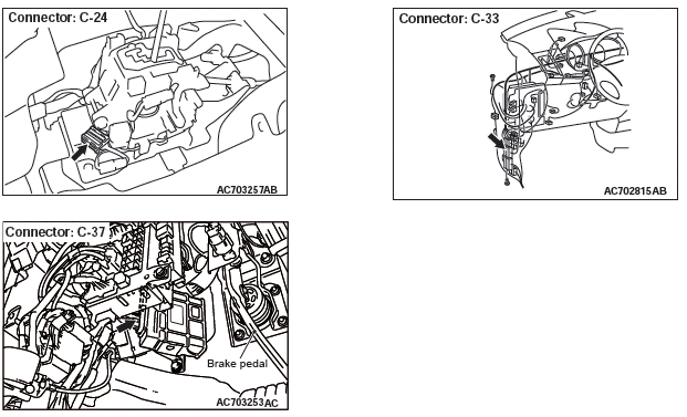
STEP 3. Check the following connector:
- C-24 selector lever assembly connector
- C-37 TCM connector
- C-33 intermediate connector
Check the terminals for a contact status problem and internal short circuit.
Q: Is the check result normal?
YES : Go to Step 4.
NO : Repair the connector concerned.
STEP 4. Check for open circuit and short to ground in the wiring harness between the selector lever assembly connector and the TCM connector.
- Between C-24 selector lever assembly connector (terminal No.6) and body ground
- Between C-24 selector lever assembly connector (terminal No.8) and C-37 TCM connector (terminal No.35)
- Between C-24 selector lever assembly connector (terminal No.9) and C-37 TCM connector (terminal No.44)
- Between C-24 selector lever assembly connector (terminal No.10) and C-37 TCM connector (terminal No.43)
- Between C-24 selector lever assembly connector (terminal No.8) and body ground
- Between C-24 selector lever assembly connector (terminal No.9) and body ground
- Between C-24 selector lever assembly connector (terminal No.10) and body ground
Q: Is the check result normal?
YES : Go to Step 5.
NO : Repair the wiring harness.
STEP 5. Retest the system.
Q: Does the malfunction take place again?
YES : Replace TCM.
NO : Intermittent malfunction
Inspection Procedure 6: Cannot be Changed with the Paddle Shift.
Paddle shift switch system circuit

SYMPTOMS
The transaxle does not upshift or downshift when the paddle shift is operated.
PROBABLE CAUSES
- Malfunction of paddle shift switch
- Damaged wiring harness and connectors
- Malfunction of TCM
DIAGNOSTIC PROCEDURE
STEP 1. M.U.T.-III data list
- Item 54: Paddle switch (up)
- Item 55: Paddle switch (down)
Q: Is the check result normal?
YES : Intermittent malfunction
NO : Go to Step 2.
STEP 2. Check the following connector:
- C-38 TCM connector
- C-208 paddle shift switch connector
- C-34 intermediate connector
Check the contact status of the terminals.
Q: Is the check result normal?
YES : Go to Step 3.
NO : Repair the damaged connector.
STEP 3. Paddle shift switch single unit check
Q: Is the check result normal?
YES : Go to Step 4.
NO : Replace the paddle shift assembly.
STEP 4. Check for open circuit in the wiring harness between the TCM connector and the paddle shift switch connector
- Between C-38 TCM connector (terminal No.22) and C-208 paddle shift switch connector (terminal No.1)
- Between C-38 TCM connector (terminal No.21) and C-208 paddle shift switch connector (terminal No.3)
- Between C-208 paddle shift switch connector (terminal No.2) and the body ground
Q: Is the check result normal?
YES : Go to Step 5.
NO : Repair the wiring harness.
STEP 5. Retest the system.
Q: Is the check result normal?
YES : Intermittent malfunction
NO : Replace TCM.
Inspection Procedure 7: The fluid temperature warning lamp illuminates too frequently.
PROBABLE CAUSES
- Thermal deterioration of the transmission fluid
- Damaged wiring harness and connectors
- Malfunction of the transmission fluid temperature sensor
- Clogged coolant system
- Clogged air-cooled transmission fluid cooler system
- Malfunction of the thermo valve
- Malfunction of TCM
- Malfunction of CVT assembly
DIAGNOSTIC PROCEDURE
STEP 1. Scan tool MB991958 special function
Check the deterioration level of the transmission fluid.
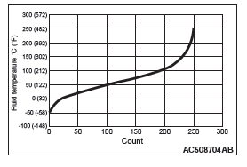
NOTE: The transmission fluid deterioration level is the accumulation of the values counted depending on the fluid temperature of a certain period of time, and it shows the thermal deterioration level of the transmission fluid.
Q: Is the deterioration level of the transmission fluid less than 210,000?
YES : Go to Step 2.
NO : Replace the transmission fluid.
STEP 2. M.U.T.-III data list
Item 5: Transmission fluid temperature sensor.
Q: Is the check result normal?
YES : Go to Step 3.
NO : Diagnostic trouble code No.P0710: Diagnose the transmission fluid temperature sensor.
STEP 3. Air-cooled transmission fluid cooler system clogging check
Check if the air-cooled transmission fluid cooler system is clogged according to the following procedure.
CAUTION Do not reuse the drained transmission fluid.
- Remove the transmission fluid cooler hose assembly.
- Blow air into the transmission fluid cooler hose assembly, and check that the air comes out from the opposite side.
- Blow air into the air-cooled transmission fluid cooler (A in the figure), and check that the air comes out from the opposite side (B in the figure).
- Install the parts, and replenish the transmission fluid to the specified quantity.
Q: Is the check result normal?
YES : Go to Step 4.
NO : Replace the part(s) having damage or other problems.

STEP 4. Thermo valve check
Q: Is the check result normal?
YES : Go to Step 5.
NO : Replace the thermo valve.
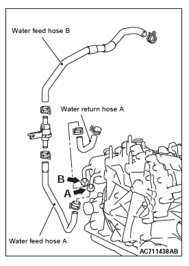
STEP 5. Coolant system clogging check
Check if the coolant system is clogged according to the following procedure.
CAUTION Do not reuse the drained coolant.
- Drain the coolant.
- Remove water feed hose A, water feed hose B and water return hose A.
- Blow air into the removed parts, and check that the air comes out from the opposite side.
- Blow air into the coolant outlet (A in the figure), and check that the air comes out from the opposite side (B in the figure).
- Install the parts, and replenish the coolant to the specified quantity.
Q: Is the check result normal?
YES : Go to Step 6.
NO : Replace the part(s) having damage or other problems.

STEP 6. Retest the system.
Q: Does a malfunction take place again?
YES : Replace the CVT assembly.
NO : Intermittent malfunction
DATA LIST REFERENCE TABLE


NOTE: *: Relation between fluid temperature and COUNT is shown to the characteristics chart.

TCM TERMINAL VOLTAGE REFERENCE CHART FOR TRANSAXLE OPERATION


OSCILLOSCOPE INSPECTION PROCEDURES
With the connector remain connected, connect the oscilloscope probe to each terminal of TCM.

Special Tool


