Mitsubishi Outlander: Power Steering Gear Box and Linkage
REMOVAL AND INSTALLATION
CAUTION
- Before removing the steering wheel and driver's airbag module, refer to GROUP 52B − Service Precautions and Driver's Airbag Module and Clock Spring. Position the front wheels in a straight ahead direction. If you fail to do this, the clock spring for SRS may be damaged, making the SRS (air bag) inoperable which may cause serious injury to the driver.
- The bolts marked with * are coated with the friction coefficient stabilizer. When removed these parts, make sure that they are free of damage, remove any dust and dirt on the bearing surfaces and the threads, and tighten to the specified torque.
- After installation, perform a calibration for the ASC-ECU to learn the steering wheel sensor neutral point. <Vehicles with ASC>.
Pre-removal operation
- Power Steering Fluid Draining
- Steering Wheel Assembly and Driver's Air Bag Module Removal
- Steering Shaft Cover Removal
- Engine room Under Cover Front (A,B,C), Engine room Side Cover, Engine room Under Cover Rear Removal
- Front Exhaust Pipe Removal
- Front Roll Stopper And Centermember Assembly Removal
Post-installation operation
- Front Roll Stopper And Centermember Assembly Installation
- Front Exhaust Pipe Installation
- Engine room Under Cover Front (A,B,C), Engine room Side Cover, Engine room Under Cover Rear Installation
- Using your fingers, press the dust cover of each joint to check for a crack or damage.
- Steering Shaft Cover Installation
- Steering Wheel Assembly and Driver's Air Bag Module Installation
- Power Steering Fluid Refilling and Bleeding
- Steering wheel straight-ahead position check
- Wheel Alignment Check and Adjustment
<2.4L Engine>
<3.0L>
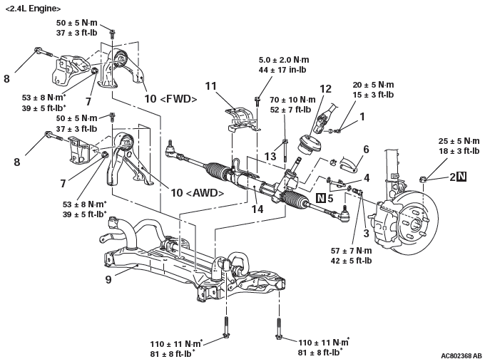
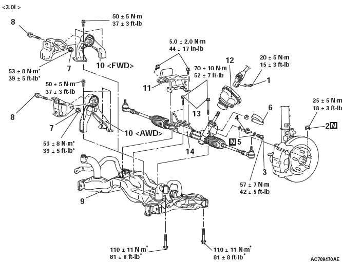
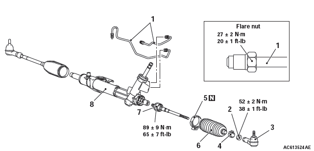
Removal steps
- Steering gear and joint connecting bolt
- Self-lock nut (Tie-rod end and knuckle connection)
- Eye bolt
- Pressure hose connection
- Gasket
- Return hose connection
- Flanged nut
- Engine rear roll stopper bracket connecting bolt
- Front axle crossmember
- Engine rear roll stopper
- Heat protector
- Joint cover grommet
- Flanged bolt
- Steering gear and linkage
Required Special Tools:
- MB991897 or MB992011: Ball joint remover
REMOVAL SERVICE POINTS
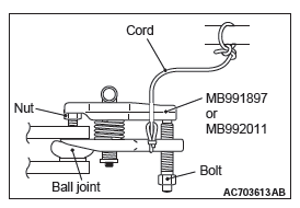
SELF-LOCK NUT (TIE-ROD END AND KNUCKLE CONNECTION) REMOVAL
CAUTION
- Loosen the self-lock nut (tie-rod end and knuckle connection) from the ball joint (Do not remove). Use the special tool for the self-lock nut removal.
- To prevent the special tool from dropping off, suspend it with a rope.
1. Install the special tool ball joint remover (MB991897 or MB992011) as shown in the figure.
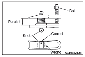
2. Turn the bolt and knob to make the special tool jaws parallel, then hand-tighten the bolt. After tightening, check that the jaws are still parallel.
NOTE: To adjust the special tool jaws to be parallel, set the orientation of the knob as shown in the figure.
3. Unscrew the bolt to disconnect the ball joint.
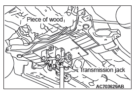
FRONT AXLE CROSSMEMBER REMOVAL
1. Jack up and support the crossmember, and remove it.
2. Check the hoses and harnesses for roughness, and then remove the front axle No.1 crossmember assembly with the rear roll stopper and the steering gear and linkage installed.
INSTALLATION SERVICE POINT
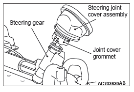
JOINT COVER GROMMET INSTALLATION
Install the joint cover grommet to the steering gear and linkage by aligning the mating marks as shown in the figure.
INSPECTION
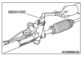
PINION TOTAL ROTATION TORQUE CHECK
CAUTION Secure the steering gear & linkage to the special mounting point. Fixing the steering gear & linkage to another point could deform or damage the gear housing.
1. Use the preload socket (Special tool: MB991006) to rotate the pinion at a rate of one turn per 4 to 6 seconds, and then measure the pinion total rotation torque.
Standard value:
Total rotation torque: 0.6 - 1.6 N*m (5.3 - 14.2 in-lb)
Torque fluctuation: 0.4 N*m (3.5 in-lb) or less
NOTE:
- During measurement, remove the bellows from the gear housing.
- Rotate the pinion by 180º in left and right directions from the neutral position, and measure the pinion total rotation torque.
2. If the measurement value is outside the standard value, replace the gear housing.
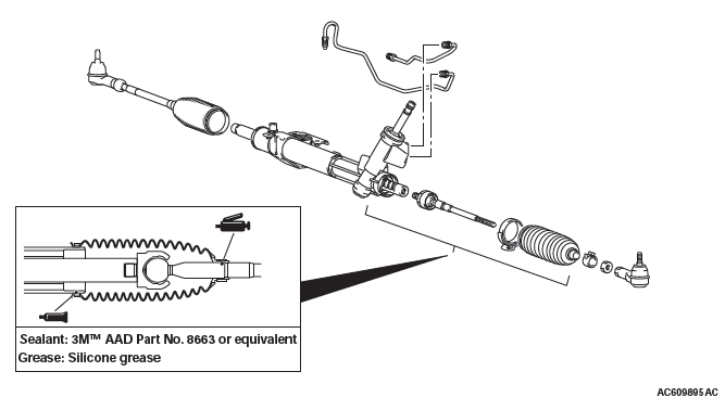
DISASSEMBLY AND ASSEMBLY
Disassembly steps
- Feed pipe
- Jam nut
- Tie-rod end
- Clip
- Band
- Bellows
- Tie-rod
- Gear housing
Required Special Tool:
- MB992209: Boot band clipping tool
- MB992249: Variable spanner
LUBRICATION AND SEALING POINTS
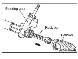
DISASSEMBLY SERVICE POINT
TIE-ROD REMOVAL
1. Move the bellows and pull the rack bar toward arrow direction.
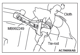
CAUTION Do not tighten the vise strongly in order not to damage the rack bar.
2. Wrap rack bar with cloth in order not to damage, and tix the rack bar with a vise.
3. Use special tool variable spanner (MB992249) to remove the tie-rod.
ASSEMBLY SERVICE POINTS
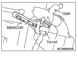
TIE-ROD INSTALLATION
CAUTION Do not tighten the vise strongly in order not to damage the rack bar.
1. Wrap rack bar with cloth in order not to damage, and tix the rack bar with a vise.
2. Use special tool variable spanner (MB992249) to tighten the tie-rod to the specified torque.
Tightening torque: 89 +- 9 N*m
BAND INSTALLATION
CAUTION
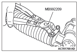
- Hold the rack housing, and use special tool bellows band crimping tool (MB992209) to crimp the bellows band securely.
- Crimp the bellows band until special tool (MB992209) touches the stopper.
1. Use special tool boot band crimping tool (MB992209) to crimp the bellows band.
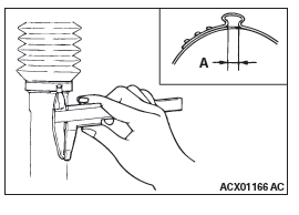
2. Check that crimped width (A) is within the standard value.
Standard value (A): 2.4 − 2.8 mm
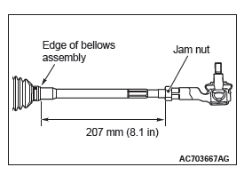
TIE-ROD END/JAM NUT INSTALLATION
Screw in the tie-rod to the length shown in the figure, and hand-tighten the jam nut.
NOTE: Install the steering gear and linkage to the body, adjust the toe-in, and then tighten the jam nut to the specified torque.
READ NEXT:
 Power Steering Oil Pump
Assembly
Power Steering Oil Pump
Assembly
REMOVAL AND INSTALLATION
Pre-removal operation
Power Steering Fluid Draining
Engine Upper Cover Removal
Engine Room Side Cover (RH) Removal
Generator and Others Belt Removal
Post-installation
Power Steering Hoses
REMOVAL AND INSTALLATION
Pre-removal operation
Power Steering Fluid Draining
Engine room Under Cover Front (A,B,C), Engine room
Side Cover, Engine room Under Cover Rear Removal
Propeller Shaft A
SEE MORE:
How To Diagnose (Electrical)
HOW TO DIAGNOSE
The most important point in troubleshooting is to
determine "Probable Cause". Once the probable
causes are determined, parts to be checked can be
limited to those associated with such probable
causes. The determination of the probable causes
must be based on a theory and be supported
Keys
Type 1, Type 2
Two keys are provided. The keys fit all locks.
Keep one in a safe place as a spare key.
1- Key for the electronic immobiliser.
2- Key number tag.
1- Key for the electronic immobiliser and keyless entry system.
2- Key number tag.
Type 3
Two keyless operation key and two eme
